PHL series is used in various fields such as food & beverage, pharmaceuticals, petrochemicals, electronics & semiconductor and medicine

GSA’s desiccant air dryer is able to provide even super-dry compressed air according to user needs

PHL Desiccan Air Dryer Series

Why Desiccant Air Dryer?

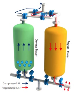
A refrigerated air dryer chills and dehumidifies compressed air, using a refrigerant. To prevent condensate generated while cooling compressed air from being frozen or a heat exchanger from being frozen-burst, dew points are usually kept at 0℃ or higher. For moisture-sensitive processes, therefore, a desiccant air dryer is essential.

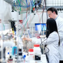
In general, a desiccant air dryer offers -40℃ or lower temperature of dew points. It is used in various fields such as food & beverage, pharmaceuticals, petrochemicals, electronics & semiconductor and medicine. In these industries, even a small amount of water might result in process discontinuance or product defect. Therefore, a highly reliable desiccant air dryer is a must-have system.

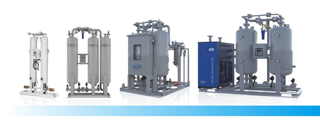
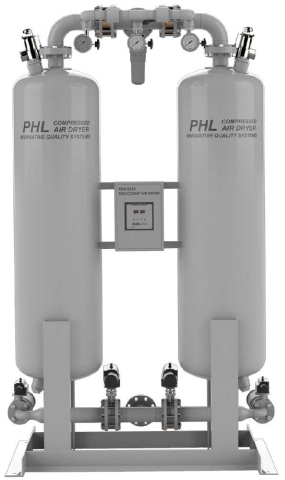
GSA’s desiccant air dryer is able to provide even super-dry compressed air (-100℃ or below) according to user needs. We have enhanced customer satisfaction through the design of diverse desiccant air dryer systems.

Classification

  • A commonly used model with a short process cycle (nearly 10 minutes)
  • Simple structure and low power consumption
  • About 14% purge consumption
  • A model with a long process cycle (8 hours orlonger)
  • A heater needed to heat regeneration air mounted
  • About 8% purge consumption
  • A model with a long process cycle (8 hours orlonger)
  • Regenerates a desiccant, using air around the blower and heaterfurnace
  • About 3% purge consumption
  • A model with a long process cycle (8 hours orlonger)
  • Regenerates a desiccant, using air around the blower and heaterfurnace
  • Zero purge consumption

Operating Mechanism

Compressed air with high moisture flows into the drying tower. While it moves from the bottom to the top of the tower, moisture is adsorbed by the charged desiccant, producing dry compressed air. While the air is being dried in the drying tower, other towers engage in regeneration process to remove adsorbed moisture. During the regeneration process, dry compressed air from the drying tower is partially used. The dry compressed air is discharged to the outside through a muffler at the bottom of the regeneration tower after moisture adsorbed into the desiccant is removed. Once the regeneration tower process is complete, the purge valve from the regeneration tower is closed. Then, dynamic pressure process pressurizing regeneration tower starts. Once the dynamic pressure process is done, two towers are transferred. In the drying tower, then, the regeneration process is executed. In the towers where such regeneration process is completed, drying process is executed.

A series of above processes are automatically repeated according to specific time and sequence, producing dry air consecutively. In terms of an operating cycle, it is basically operated for 10 minutes. Drying process is executed by two towers (5 minutes each). Specifically, it is regenerated for 4 minutes with 1 minute dynamic pressure.

operating mechanism

Desiccant Air Dryer for Stable Dew Points

Desiccant Air Dryer with Diverse Features

PEH series
  1. Minimization of Purge Air Loss

    Minimizes compressed air loss through accurately calculated orifice caliber and precision processing

  2. TEFLON CHECK Valve

    Noise minimized with TEFLON check valves

  3. SAFETY VALVE

    Ensures safety with KOSHA-certified safety valves

  4. High-quality Pressure Gauge

    High performances and low faults with highly reliable pressure gauges including WIKA products

  5. CONTROL AIR FILTER

    A control-purpose compressed air filter installed to prevent valves and pneumatic solenoid valves from malfunctioning

  6. Precise Processing Time Control

    Able to set drying/dynamic pressure time to seconds; efficient operation enabled by controlling processing time depending on operating conditions

  7. PARKER Pneumatic Solenoid Valve

    Able to check operating conditions easily, using PARKER’s LED pneumatic solenoid valve

  8. High-quality Desiccant

    Stabledewpointswith high-quality active alumina including those with 0.42ml/g or higher porosity

  9. Efficient Compressed Air Distribution System

    A bottom distributor installed to prevent the bias flow of compressed air in a large adsorption tower and provide stable dew points

  10. Highly Reliable Auto Valve

    Proven angle sheet and butterfly valves used

  11. High-quality Muffler

    Minimizes noise from the purge with an Allied Witan’s muffler

Technical Specification

Design Conditions

  • Inlet Pressure : 7 barg
  • Inlet Temperature : 38 ℃
  • Dew Points : -40 ℃ @ ATM
  • Design Temperature : 250 ℃
  • Design Pressure : 9.7 barg
  • Differential Pressure : 0.2 barg

References

  • Those with - 40℃ or below dew points are also customizable.
  • ASME specifications in addition to KS are also customizable.
  • A unit with 9.7barg or higher operating pressure is custom-made.
  • Special-purpose models in addition to the proposed specifications are also customizable.
  • The specifications are subject to changes without notice for product improvement.
peh size
*Note 1: Desiccant Amount of 2 Towers / *Note 2: Total Weight
Model Connection Flow Rate Air Compressor Power Consumption Power Supply Dimensions (mm) Desiccant Amount
*Note 1
Weight
*Note 2
A N㎥/hr HP W V / Ph / Hz A B C kg/2Tower kg
P
H
L
100 PT 20A 160 20 50 220 / 1 /
50, 60
1000 470 1495 48 170
150 PT 25A 240 30 1000 470 1495 60 260
200 PT 40A 320 40 1200 560 1642 97 320
285 PT 40A 450 50 1200 560 1642 121 400
350 PT 40A 550 60 1400 630 1705 129 450
430 PT 40A 680 75 1400 630 1705 160 500
560 PT 50A 890 100 1500 680 2036 213 560
720 PT 50A 1140 130 1500 680 2036 266 650
900 FLG. 65A 1430 150 1800 750 2251 325 700
1100 FLG. 65A 1740 175 1800 750 2251 406 780
1350 FLG. 80A 2140 200 1900 995 2338 480 900
1550 FLG. 80A 2450 250 1900 995 2338 593 1000
2100 FLG. 100A 3320 2650 2300 1170 2849 755 1500
2600 FLG. 100A 4120 400 2300 1170 2849 943 1700
3000 FLG. 125A 4750 500 2650 1295 3005 1065 2000
3400 FLG. 125A 5380 600 2650 1295 3005 1243 2250
4100 FLG. 125A 6490 700 3100 1653 2307 1455 2800
4500 FLG. 125A 7120 800 3100 1653 2307 1620 3000

Correction Factors

Correction Factor by Inlet Air Temperature
Inlet Air Temperature (℃) 27 32 38 43 49 N/A N/A N/A N/A N/A N/A N/A
Correction Factor 1.14 1.12 1.00 0.75 0.65 N/A N/A N/A N/A N/A N/A N/A
Correction Factor by Inlet Air Pressure
Inlet Air Pressure (barg) 3 4 5 6 7 8 9 N/A N/A N/A N/A N/A
Correction Factor 0.37 0.55 0.75 0.87 1 1.16 1.24 N/A N/A N/A N/A N/A
Certification mark