PEH series is used in various fields such as food & beverage, pharmaceuticals, petrochemicals, electronics & semiconductor and medicine

GSA’s desiccant air dryer is able to provide even super-dry compressed air according to user needs

PEH Desiccant Air Dryer Series

Why Desiccant Air Dryer?

A refrigerated air dryer chills and dehumidifies compressed air, using a refrigerant. To prevent condensate generated while cooling compressed air from being frozen or a heat exchanger from being frozen-burst, dew points are usually kept at 0℃ or higher. For moisture-sensitive processes, therefore, a desiccant air dryer is essential.

In general, a desiccant air dryer offers -40℃ or lower temperature of dew points. It is used in various fields such as food & beverage, pharmaceuticals, petrochemicals, electronics & semiconductor and medicine. In these industries, even a small amount of water might result in process discontinuance or product defect. Therefore, a highly reliable desiccant air dryer is a must-have system.

GSA’s desiccant air dryer is able to provide even super-dry compressed air (-100℃ or below) according to user needs. We have enhanced customer satisfaction through the design of diverse desiccant air dryer systems.

Classification

  • A commonly used model with a short process cycle (nearly 10 minutes)
  • Simple structure and low power consumption
  • About 14% purge consumption
  • A model with a long process cycle (8 hours orlonger)
  • A heater needed to heat regeneration air mounted
  • About 8% purge consumption
  • A model with a long process cycle (8 hours orlonger)
  • Regenerates a desiccant, using air around the blower and heaterfurnace
  • About 3% purge consumption
  • A model with a long process cycle (8 hours orlonger)
  • Regenerates a desiccant, using air around the blower and heaterfurnace
  • Zero purge consumption

Operating Mechanism

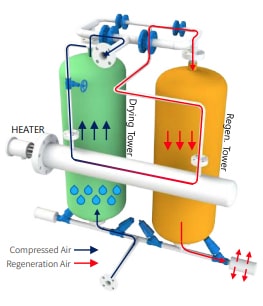
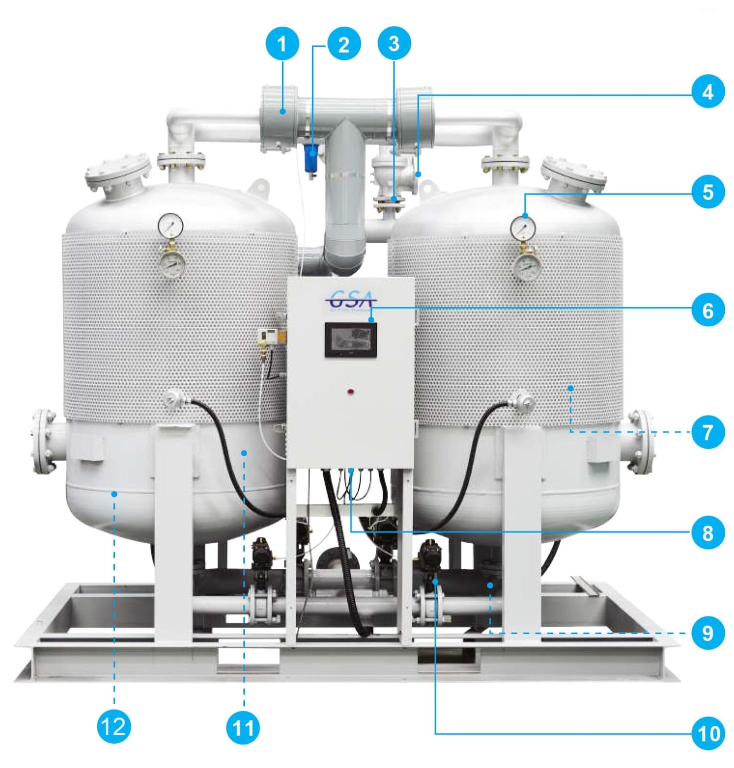
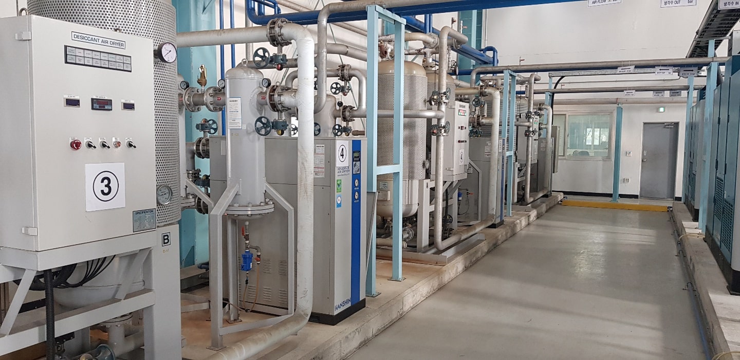
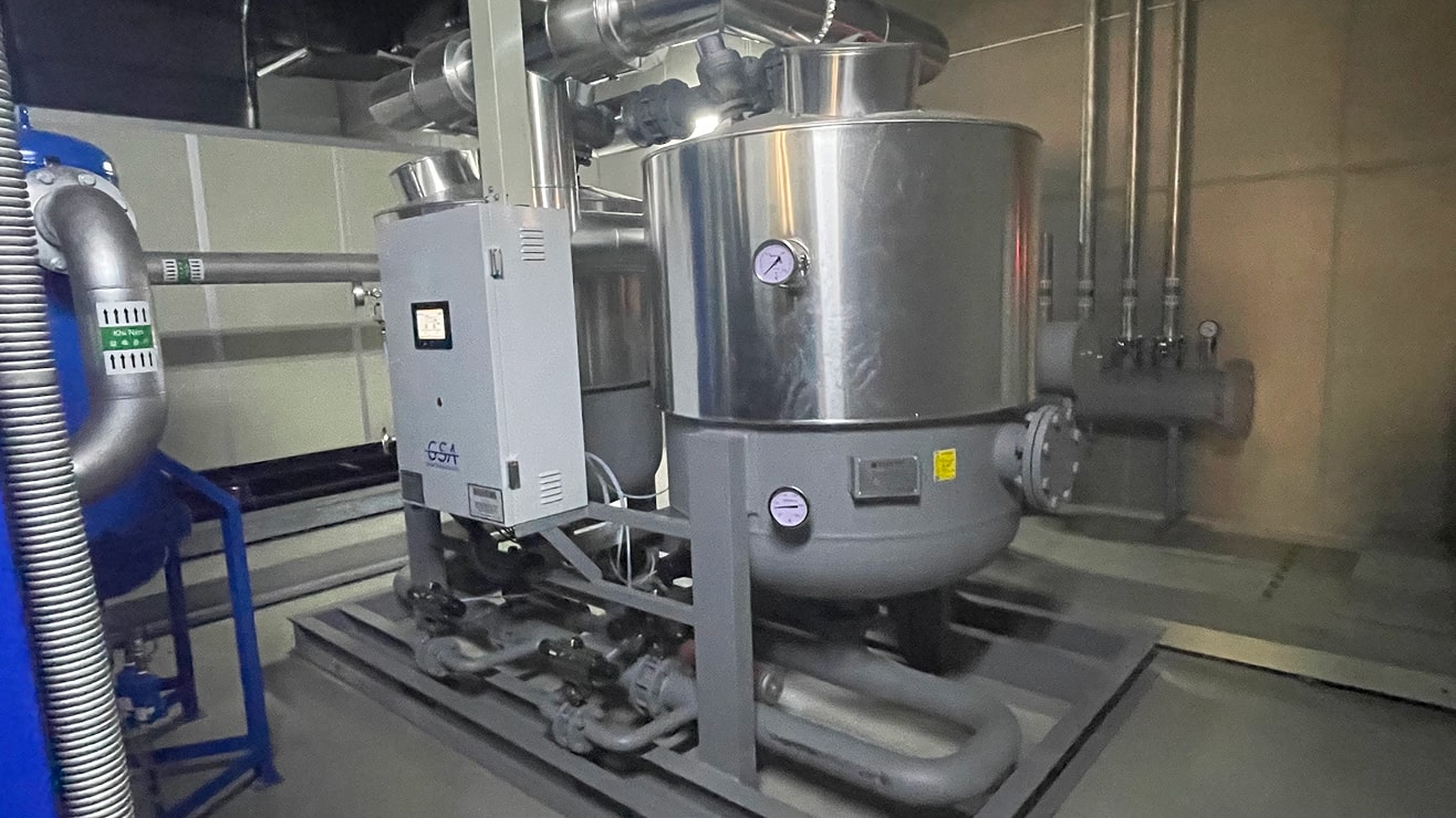
Compressed air with high moisture flows into the drying tower. While it moves from the bottom to the top of the tower, moisture is adsorbed by the charged desiccant, producing dry compressed air. While the air is being dried in the drying tower, other towers engage in regeneration process to remove adsorbed moisture. During the regeneration process, dry compressed air from the drying tower is partially used. The dry compressed air at the outlet is heated by an electric heater, and moisture adsorbed by the desiccant in the regeneration tower is desorbed and discharged through a muffler at the bottom. Once the heating process is complete, heater operation is stopped, and the cooling process begins. The cooling process is a process to enhance adsorbing performances by cooling down the heated desiccant. Once the
cooling process is completed, the desiccant regeneration process from the regeneration tower is also finished. The purge valve from the regeneration tower is closed. Then, dynamic pressure process pressurizing regeneration tower starts. Once the dynamic pressure process is done, two towers are transferred. In the drying tower, then, the regeneration process is executed. In the towers where such regeneration process is completed, drying process is executed.

A series of above processes are automatically repeated according to specific time and sequence, producing dry air consecutively. In terms of an operating cycle, it is basically operated for 8 hours. Drying process is executed by two towers (4 hours each). Specifically, it is heated for 2 hours and 30 minutes and cooled for 1 hour and 27 minutes with 3-minute dynamic pressure.

operating mechanism PEH

Desiccant Air Dryer for Stable Dew Points

Desiccant Air Dryer with Diverse Features

PEH series
  1. PAN/DUAL Check Valve

    High-performance PAN/dual check valves with a little chance of breakdown used

  2. CONTROL AIR FILTER

    A control-purpose compressed air filter installed to prevent valves and pneumatic solenoid valves from malfunctioning

  3. Minimization of Purge Air Loss

    Minimizes compressed air loss through accurately calculated orifice caliber and precision processing

  4. SAFETY VALVE

    Ensures safety with KOSHA-certified safety valves

  5. High-quality Pressure Gauge

    High performances and low faults with highly reliable pressure gauges including WIKA products

  6. PLC and Touchpanel

    A touchpanel designed for PLC and user convenience applied; able to operate and get diverse information easily

  7. High-quality Desiccant

    Stable dew points with high-quality active alumina including FRANCE AXENS

  8. PARKER Pneumatic Solenoid Valve

    Able to check operating conditions easily, using PARKER’s LED pneumatic solenoid valve

  9. High-quality Muffler

    Minimizes noise from the purge with an Allied Witan’s muffler

  10. Highly Reliable Auto Valve

    Proven angle sheet and butterfly valves used

  11. Electric Heater

    An immersion heater with very low heat loss and great heating performances used

  12. Efficient Compressed Air Distribution System

    A bottom distributor installed to prevent the bias flow of compressed air in a large adsorption tower and provide stable dew points

Technical Specification

Design Conditions

  • Inlet Pressure : 7 barg
  • Inlet Temperature: 38 ℃
  • Dew Points : -40 ℃ @ ATM
  • Design Temperature : 250 ℃
  • Design Pressure : 9.7 barg
  • Differential Pressure : 0.2 barg

References

  • Those with - 40℃ or below dew points are also customizable.
  • ASME specifications in addition to KS are also customizable.
  • A unit with 9.7barg or higher operating pressure is custom-made.
  • Special-purpose models in addition to the proposed specifications are also customizable.
  • Large models bigger than those stated in the specifications above are also customizable.
  • The specifications are subject to changes without notice for product improvement.
peh size
*Note 1: Desiccant Amount of 2 Towers / *Note 2: Total weight
Model Connection Flow Rate Air Compressor Heater Power Supply Dimensions(mm) Desiccant Amount
*Note 1
Weight
*Note 2
A N㎥/hr HP kW V / Ph / Hz A B C kg/2Tower kg
P
E
H
100 FLG. 20A 160 20 1.5 220V
380V
440V
/ 1 Ph
/ 50, 60Hz
800 420 1570 60 260
150 FLG. 25A 240 30 2.0 1100 510 1690 97 320
200 FLG. 40A 320 40 2.5 1300 850 1770 121 480
285 FLG. 40A 450 50 3.5 1300 850 1770 160 530
350 FLG. 40A 550 60 4.5 1600 880 2030 213 780
430 FLG. 40A 680 75 5.5 1600 900 2030 266 880
560 FLG. 50A 890 100 7.0 1700 1000 2230 324 1100
720 FLG. 50A 1140 130 9.0 1700 1000 2230 406 1350
900 FLG. 65A 1430 150 11.0 2200 1250 2400 500 1550
1100 FLG. 80A 1740 175 13.5 2200 1250 2400 593 1850
1350 FLG. 80A 2140 200 16.5 2200 1670 2330 754 2350
1550 FLG. 80A 2450 250 19.0 2200 1710 2330 943 2750
2100 FLG. 100A 3320 300 25.5 2650 1650 2445 1243 3600
2600 FLG. 100A 4120 400 31.5 2850 1970 2290 1442 3900
3000 FLG. 125A 4750 500 36.0 3050 1970 2290 1620 4500
3400 FLG. 125A 5380 600 41.0 3150 2140 2530 1883 4900
4100 FLG. 125A 6490 700 50.0 3150 2180 2530 2310 5300
4500 FLG. 150A 7120 800 55.0 5000 2000 2960 2494 5600
5400 FLG. 150A 8550 900 65.0 5000 2000 2690 3056 6200
6000 FLG. 150A 9500 1000 73.0 5300 2100 3000 3325 6900

Correction Factors

Correction Factor by Inlet Air Temperature
Inlet Air Temperature (℃) 27 32 38 43 49 N/A N/A N/A N/A N/A N/A N/A
Correction Factor 1.14 1.12 1 0.75 0.65 N/A N/A N/A N/A N/A N/A N/A
Correction Factor by Inlet Air Pressure
Inlet Air Pressure (barg) 4 5 6 7 8 9 N/A N/A N/A N/A N/A N/A
Correction Factor 0.6 0.75 0.87 1 1.16 1.24 N/A N/A N/A N/A N/A N/A
Certification mark