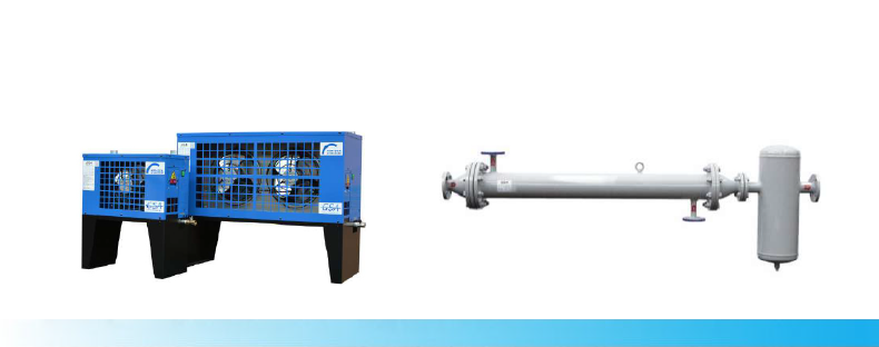
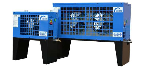
The compressed air from air compressor is provided at temperature higher than ambient temperature by nearly 15℃ due to the heat pro�duced during compression. Such hot and humid compressed air increases load on a refrigerated or desiccant air dryer, reducing dehumidifying performances by increasing load on dehumidifying systems such as a refrigerated/desiccant air dryer.
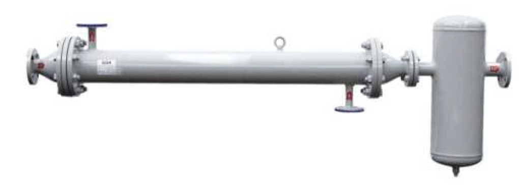
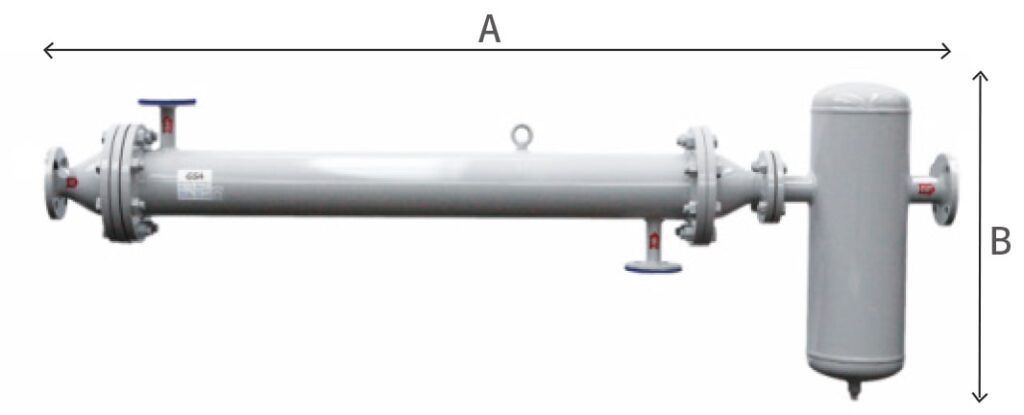
An after-cooler is an auxiliary system designed to enhance dehumidifying performances by lowering load on a refrigerated or desiccant dryer by cooling high-temperature compressed air and discharging condensate.